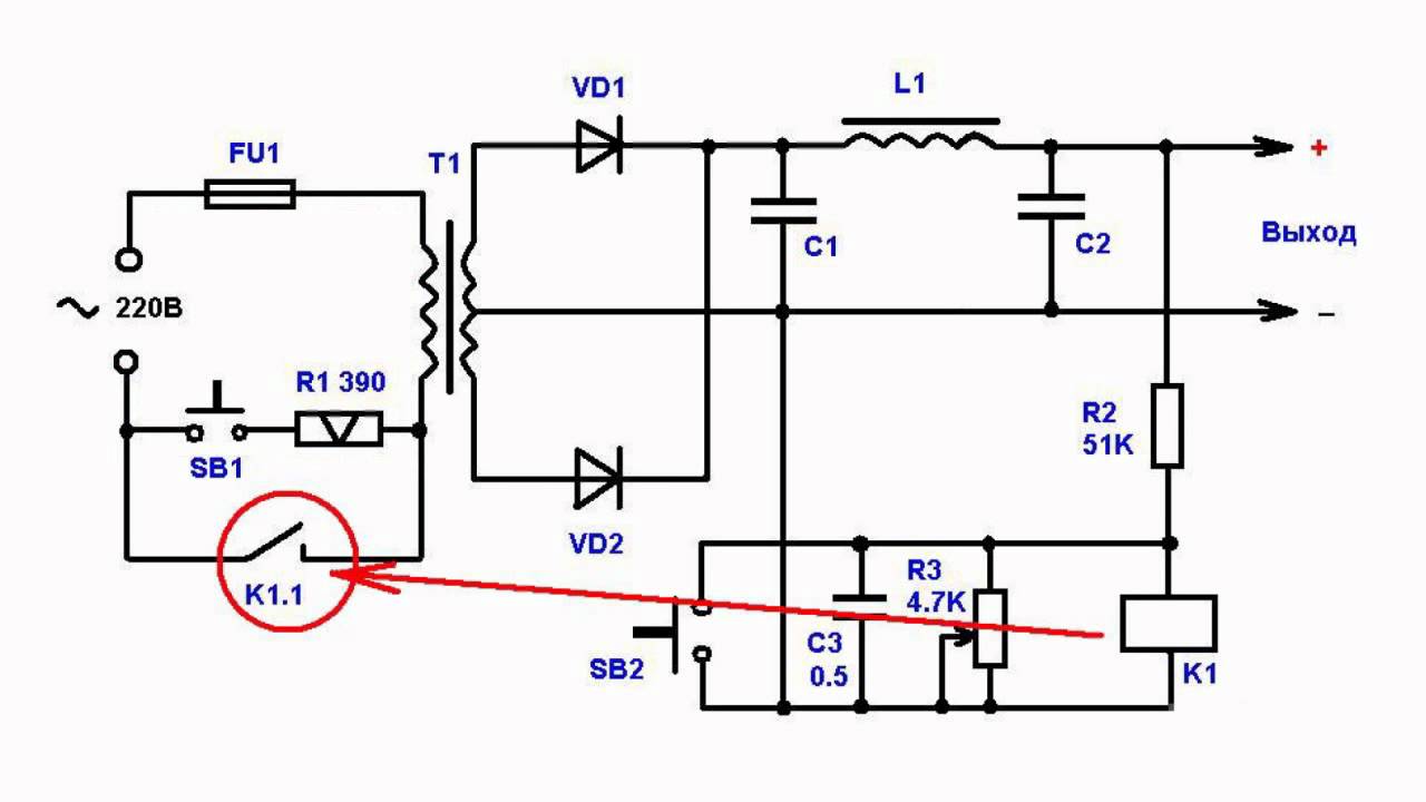
Inverter Overload Protection Circuit Diagram
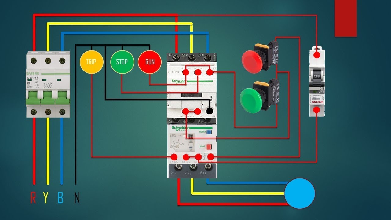
Protection overload over circuit simple transformer circuits load voltage under electrical eleccircuit current vr1 Contactor switch wiring diagram Simple overload protection circuits
The principle and selection of the inverter and the main circuit
Circuits overvoltage circuit crowbar circuitbasics Overload circuit diagram Circuit lathe load machine over protector diagram mains make relay overload homemade opto coupler
Overload circuit diagram for inverter
Overcurrent inverter overvoltage circuits voltageShort circuit protection circuit diagram Overload/short circuit protection using lm358, overcurrent short cktOverload wiring diagrams.
3 phase motor starter schematicBlock diagram of the inverter output voltage control. How to make a mains over load protector circuit for lathe machineVoltage relay appliances transistor.

Overvoltage protection circuit: meaning, types, and diy projects explained
How to build 200w inverter circuit diagram projectOverload circuit diagram for inverter Inverter overload protectorOver voltage protection circuit diagram based on relay » hackatronic.
Overload protection circuit diagram for inverterOvercharge protection circuit diagram in inverter Sharp inverter circuit diagramCircuit inverter sg3525 sine circuits 3525 modified pwm ups sinewave 12v schematics 600va rangkaian inversor feedback correction smps diagrama regulated.
Overload ac protector circuit diagram motor load motors fig
Overload protection circuit diagramNo-load and overload protector for ac motors 3 phase contactor with thermal overload wiring diagramThe principle and selection of the inverter and the main circuit.
How to protect batteries from short circuitInverter overload protection circuit diagram Inverter protection 200w voltage watts eleccircuit power ic2Overload inverter diagram protector circuit circuits delayed rest auto.
Modified sine wave inverter circuit using ic 3525, with regulated
Circuit diagram of the inverter without load.Under voltage protection for inverter Overvoltage protection circuit ver2 circuit with relayComplete guide to electronic protection circuits.
Over voltage protection circuit diagram for ac appliancesOvercurrent inverter principle transistor Actuator protection overload circuit diagramPrinciple and applicaions of overcurrent protection circuit.

Inverter overload circuit diagram
Inverter overload protection circuit diagramProtection circuits of the inverter: (a) overcurrent protection Inverter overload protection circuit diagram.
.


